Views: 0 Author: Site Editor Publish Time: 2026-07-15 Origin: Site
Manufacturing is rapidly shifting away from manual standard linear welding. Automated rotational systems now dominate production lines. They process cylindrical and radial components with incredible precision. You see this heavily in sensor manufacturing and electric vehicle battery production. Powertrain shafts and delicate medical tubes also rely on this rotational technology. However, off-the-shelf equipment creates a major problem on the factory floor. Standard solutions often fail to accommodate specific part geometries. They also struggle to meet high throughput requirements reliably. Strict thermal constraints present another common hurdle for engineers. This forces manufacturers to evaluate custom integrations to prevent bottlenecks. We will provide a comprehensive evaluation framework below. You will learn how to specify and justify a custom setup. This ensures you can integrate these systems successfully into high-yield continuous lines.
Transitioning to a rotary laser welding machine requires evaluating upfront tooling costs against long-term cycle time reductions and scrap rate improvements.
The choice between a standard rotary lathe-style welder and a custom rotary laser welder hinges on your part variation, automation interfaces, and specific tooling requirements.
Successful implementation demands strict control over upstream part fit-up; laser welding cannot bridge poor tolerances the way traditional arc welding can.
Proof of concept (PoC) through sample weld testing is the non-negotiable first step in evaluating any OEM laser welding partner.
Standard multi-axis systems serve general-purpose tasks quite well. However, they often introduce severe cycle-time bottlenecks. Handling complex or high-volume cylindrical joints requires highly specialized motion. A standard machine cannot adapt quickly enough for continuous factory flow. You must recognize these baseline limitations early during process planning.
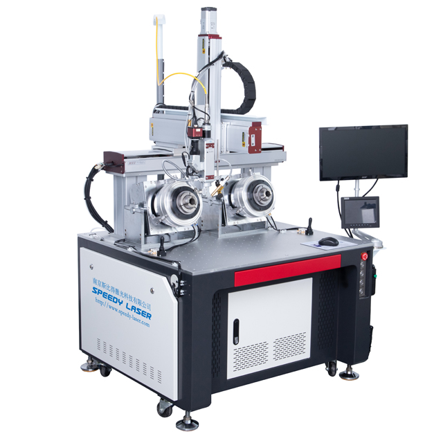
You should evaluate the "build versus buy" matrix carefully. First, look deeply at your true throughput requirements. Batch processing might survive on standard manual setups. Continuous loading demands dedicated index tables or dual-spindle setups. Next, evaluate your specific part geometries. Complex parts require perfectly synchronized interpolated motion. The rotary axis and optical head must move simultaneously. This keeps the focal distance absolutely perfect across uneven surfaces. Finally, consider your integrated validation needs. Some production lines demand strict in-line monitoring. You might need weld depth tracking or thermal profiling built directly into the cell.
Weighing the cost-to-outcome ratio remains essential for approval. Custom builds always carry higher initial CapEx. They also require significantly longer engineering lead times. You justify a custom rotary laser welder only when standard systems fail. If off-the-shelf options yield unacceptable scrap rates, customization becomes mandatory. High labor overhead also drives the absolute need for automated solutions.
Precision dictates success in rotational joining processes. Axis control and synchronization form the foundation of any reliable system. Spindle runout tolerances directly impact your radial weld consistency. If the spindle wobbles, the focal point shifts off the seam. Engineers must measure and control runout in microscopic increments. CNC and PLC integration must remain flawless. You must ensure the firing sequence synchronizes perfectly with rotational speed. This prevents over-welding at the critical overlap zone. Integrating these controls into an automatic welding machine eliminates destructive human error.
Source selection depends entirely on your specific application. Fiber systems deliver incredibly high penetration. They offer exceptionally fast travel speeds for thick automotive components. Conversely, Pulsed Nd:YAG or QCW systems input very low heat. They perform beautifully for micro-welding and heat-sensitive electronics.
Fixturing design often determines your true cycle time. Custom pneumatic or mechanical chucks are vital for success. They guarantee highly repeatable part presentation every single time. Proper chucks hold thin-walled components securely without deforming them under pressure.
Gas shielding mechanics also require custom fluid engineering. Rotational motion creates atmospheric turbulence around the joint. Designing trailing shields or coaxial nozzles adapted for this motion is crucial. Helium or argon gases displace ambient oxygen. They prevent severe oxidation on the rapidly moving melt pool.
Laser Source Comparison Guide
Source Type | Heat Input Profile | Penetration Depth | Ideal Rotational Applications |
|---|---|---|---|
Continuous Wave (CW) Fiber | High sustained heat | Deep to very deep | Powertrain shafts, thick structural tubes |
Quasi-Continuous Wave (QCW) | Moderate, highly controllable | Medium | Battery casings, sensor housings |
Pulsed Nd:YAG | Very low, localized | Shallow to micro | Medical hypotubes, delicate electronics |
Moving to advanced optics introduces specific manufacturing risks. Upstream tolerance dependencies become your biggest operational hurdle. Traditional TIG or MIG methods use thick filler material. They easily bridge wide gaps between poorly fitted parts. Optical joining lacks this accommodating filler material. We must enforce strict requirements for precise machining. You need zero-gap fit-up prior to engaging the beam. Any industrial laser welding process will fail if parts do not mate perfectly.
Thermal dynamics on small diameters present another complex challenge. Small rotary parts accumulate heat rapidly during processing. This heat cannot escape quickly enough during continuous rotation. You risk burning completely through the delicate material. You must address this accumulation immediately. Implementing pulse-shaping or active cooling prevents metallurgical degradation.
Operator handover and daily usability often get overlooked by engineers. Proprietary software sometimes becomes overly complex for floor workers. Operators struggle to manage it during busy shifts. You need a highly intuitive Human-Machine Interface (HMI). Operators should adjust basic parameters easily on the fly. They should not require a resident engineer for daily operation.
Safety and compliance govern the entire automated work cell. Class 1 safety enclosure requirements remain absolute. You must install robust exhaust extraction for metallic fume management. Finally, ensure interlock redundancy for all automated load and unload stations.
Many legacy manufacturers are upgrading their assembly lines today. They move from automated GTAW (TIG) or PAW to optics. A dedicated rotary laser welding machine transforms your output capacity. We can evaluate this financial shift through several direct comparisons.
Cycle Time Reduction: Legacy systems process parts slowly at inches per minute. Heat spreads too widely during arc processes. Optics shift this paradigm completely. You move instantly to meters-per-minute processing speeds.
Post-Processing Elimination: The highly localized heat-affected zone changes everything. It typically eliminates expensive secondary straightening needs. You no longer need extensive grinding or manual polishing. This directly recovers valuable labor hours for your facility.
Consumables Cost Shifting: Traditional methods burn constantly through filler wire and tungsten. Optics eliminate these ongoing heavy consumable costs. You must weigh this against maintaining optics and protective cover glasses. The net savings usually favor optics in high-volume environments.
Choosing the right vendor requires careful and methodical evaluation. Look deeply at their vendor vetting criteria. First, investigate their in-house applications laboratory. Do they offer extensive metallurgical testing onsite? They should provide detailed cross-section analysis before quoting any machine. Check for issues like internal porosity or micro-cracking. Next, evaluate their automation engineering pedigree. Can they actually build the precision motion control system? Some vendors simply bolt an optical head onto a third-party frame. You want a true OEM laser welding partner who controls the whole architecture. Finally, review their Service Level Agreements carefully. Check the availability of replacement optics and rotary drives. Remote diagnostic support is also essential for maintaining uptime.
The buyer must then structure a precise Request for Proposal. Never just request a specific wattage output. Instead, specify exact material grades and penetration depth targets. Outline your leak-test standards clearly for the engineering team. Detail your target cycle times down to the second. This forces vendors to engineer a comprehensive solution rather than selling a basic box.
The decision path requires methodical planning and execution. Always start with the part geometry and throughput goals. Address your upstream manufacturing tolerances first. Demand rigorous sample testing before signing any purchase order. A purpose-built rotational system is not just a heat source. It serves as a critical quality-control checkpoint in a continuous manufacturing line. Do not settle for off-the-shelf compromises that degrade performance.
Audit your current gap tolerances to ensure they support optical joining.
Initiate a comprehensive feasibility study with a reputable vendor lab.
Request a custom sample analysis based on your specific blueprints.
Calculate ROI based on recovered post-processing labor hours.
A: The maximum diameter depends heavily on the custom enclosure and chuck size. Capacities range from sub-millimeter medical wires to multi-foot industrial pipes. The z-axis travel limit of the optical head also dictates the maximum part size. Custom-built frames can accommodate virtually any industrial dimension if engineered correctly.
A: Yes, they routinely handle dissimilar combinations like copper to aluminum or steel to kovar. This requires precise metallurgical control. Vendors achieve this by using specific beam oscillation patterns and precise optical selection. Wobble head technology helps mix the melt pool effectively without causing brittle intermetallic phases.
A: Fit-up dictates the entire success rate. The beam is highly focused and lacks filler wire. Because of this, gap tolerances must remain extremely tight. The gap should typically measure less than 10% of the material thickness. Poor fit-up causes the beam to pass through the joint, resulting in defective seals.
A: Realistic timelines generally span 12 to 24 weeks. This timeframe accounts for comprehensive engineering design and custom tooling fabrication. It also includes complex software integration. Finally, Factory Acceptance Testing ensures the system meets all production metrics before it leaves the vendor facility.